電気回路図
CircuiTikzによる電気回路図作成
TikZのコーディングにおけるCircuiTikzによる電気回路図作成について解説していきます。
まず上記CircuiTikzを使用するにはTeXのプリアンブル上で以下のように記述する必要があります。
\usepackage{tikz}
\usepackage{circuitikz}
次に\begin{document}と\end{document}の本文内で\begin{figure}\end{figure}でマークアップしさらにその中で\begin{circuitikz}と\end{circuitikz}でマークアップします。
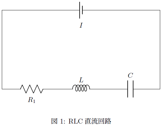
例1.RLC直列回路
 コード
コード
\begin{figure}
\begin{center}
\begin{circuitikz}
\draw (8,4) to[short] (8,0);
\draw (0,4) to [battery1,l_=$I$] (8,4);
to[short] (8,0);
\draw(3,0) to[R=$R_1$] (0,0)
to[short] (0,4)--(0,0);
\draw(3,0) to[cute inductor=$L$] (5,0);
\draw(5,0) to[C=$C$] (8,0);
\end{circuitikz}
\caption{RLC直流回路}
\end{center}
\end{figure}
出力画像
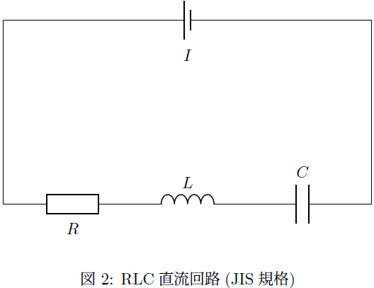
例2.RLC直列回路(JIS規格)
コード
\begin{figure}
\begin{center}
\begin{circuitikz}
\draw (8,4) to[short] (8,0);
\draw (0,4) to [battery, l_=$I$] (8,4);
to[short] (8,0);
\draw(3,0) to[european resistor=$R$] (0,0);
to[short] (0,4)--(0,0);
\draw(3,0) to[american inductor=$L$] (5,0);
\draw(5,0) to[C=$C$] (8,0);
\end{circuitikz}
\caption{RLC直流回路(JIS規格)}
\end{center}
\end{figure}
出力画像
代表的な素子画像
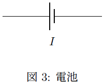
電池
コード
\begin{figure}
\begin{center}
\begin{circuitikz}
\draw (0,0) to [battery1,l_=$I$] (3,0);
\end{circuitikz}
\caption{電池}
\end{center}
\end{figure}
出力画像
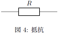
抵抗(JIS規格による)
コード
\begin{figure}
\begin{center}
\begin{circuitikz}
\draw(0,0) to[european resistor=$R$] (3,0);
\end{circuitikz}
\caption{抵抗}
\end{center}
\end{figure}
出力画像
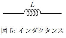
インダクタンス
コード
\begin{figure}
\begin{center}
\begin{circuitikz}
\draw(0,0) to[cute inductor=$L$] (3,0);
\end{circuitikz}
\caption{インダクタンス}
\end{center}
\end{figure}
出力画像
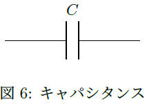
キャパシタンス
コード
\begin{figure}
\begin{center}
\begin{circuitikz}
\draw(0,0) to[C=$C$] (3,0);
\end{circuitikz}
\caption{キャパシタンス}
\end{center}
\end{figure}
出力画像
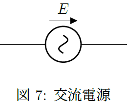
交流電源
コード
\begin{figure}
\begin{center}
\begin{circuitikz}
\draw(0,0) to[sV=$E$] (3,0);
\end{circuitikz}
\caption{交流電源}
\end{center}
\end{figure}
出力画像
詳しいアーカイブなどに関しては以下サイトを参照ください。
CTAN Comprehensive TeX Archive Network
https://www.ctan.org/pkg/circuitikz
基本的な回路図作成
直流回路、直流回路の合成抵抗図、交流回路、RLC直列回路、並列接続回路などの基本的なものの回路図の描画を扱っています。
テスト投稿
-
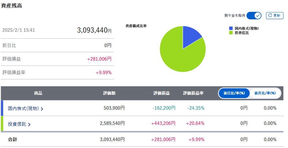
2025年1月NISA運用概況
続きを読む
-

2025年1月金運用概況
続きを読む
-
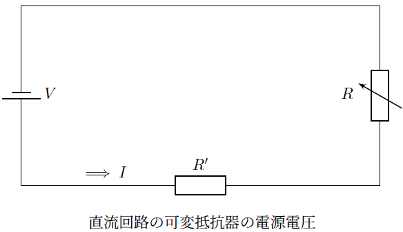
可変抵抗器の直列回路
続きを読む
-
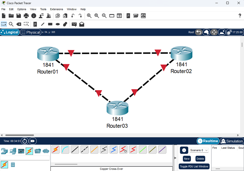
Packet Tracer
続きを読む
-
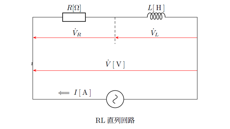
交流回路の直列接続
続きを読む
-
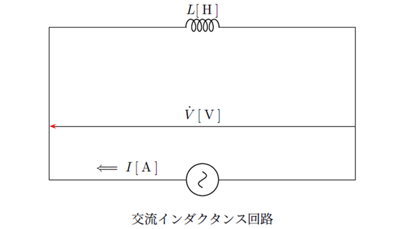
交流回路
続きを読む